
| Version 31 (modified by , 7 years ago) ( diff ) |
|---|
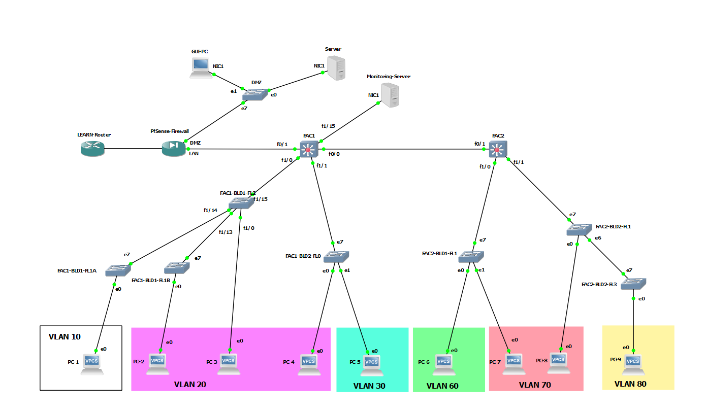
Campus Network Design - Network Setup
In this tutorial, we will establish dual-stack network connectivity within all nodes of the network given below.

IP Address Plan
| Device | Management IP Address | MGT Network | MGT VLAN |
|---|---|---|---|
| FAC1 | 10.XY.2.1 | 10.XY.2.0/24 | VLAN 2 |
| FAC1-BLD1-FL0 | | 10.XY.2.0/24 | VLAN 2 |
| FAC1-BLD1-FL1 | | 10.XY.2.0/24 | VLAN 2 |
| FAC1-BLD1-FL2 | 10.XY.2.4 | 10.XY.2.0/24 | VLAN 2 |
| FAC1-BLD2-FL0 | | 10.XY.2.0/24 | VLAN 2 |
| FAC2 | 10.XY.3.1 | 10.XY.3.0/24 | VLAN 3 |
| FAC2-BLD1-FL1 | | 10.XY.3.0/24 | VLAN 3 |
| FAC2-BLD2-FL1 | | 10.XY.3.0/24 | VLAN 3 |
| FAC2-BLD2-FL3 | | 10.XY.3.0/24 | VLAN 3 |
| FAC1 | Type | VLANS/IP | Native VLAN |
|---|---|---|---|
| F0/0 | Routed Link | 10.XY.0.6/30 2401:DD00:20XY:2::FFFF/64 | - |
| F0/1 | Routed Link | 10.XY.0.1/30 2401:DD00:20XY:1::FFFE/64 | - |
| F1/0 | Trunk | 10, 20 | 2 |
| F1/1 | Trunk | 20, 30 | 2 |
| F1/15 | Access | 5 | - |
| FAC2 | Type | VLANS/IP | Native VLAN |
|---|---|---|---|
| F0/1 | Routed Link | 10.XY.0.5/30 2401:dd00:20XY:2::FFFE/64 | - |
| F1/0 | Trunk | 60, 70 | 3 |
| F1/1 | Trunk | 70, 80 | 3 |
Log in to the the devices
In GNS3 topology right click on each network device and select Console. It will open your device console screen on a putty.
Initial Configurations
Before configuring the devices for the network setup. Let's configure some initial settings in the Core Network Devices.
Press the Enter key to go to the user mode of the FAC1 switch. Prompt will look as follows.
FAC1#
In this privileged mode, you can check the router configuration by the following command. The configuration you see will be the default configuration
FAC1#show run
To add configurations you have to go configuration mode. Type config terminal. Note the prompt change.
FAC1(config)#
note: If you get following error,
%Error opening tftp://255.255.255.255/AccessRt-confg (Timed out)
Give the following command in the config mode,
no service config
You can now start making configurations.
- The first thing you have to add is the hostname of the device. The hostname is the device's identification. In this Lab, device name or the hostname is automatically configured based on the GUI edits we did previously. If you want to change it you may use
hostname <device name>
- Then let's give a enable secret. Which is a password you set when you go to the privileged mode from the user mode? Make sure to use the <class password> as the enable secret
enable secret <class password>
- Add the DNS server
ip name-server 10.XY.0.2
In your production environment you may use your internal DNS resolver if needed.
- Next, you can add a banner to your device. This will display every time you log in to the device
banner motd @ Unauthorized Access is Prohibited! @
- Add more security by encrypting passwords in your config file
service password-encryption
- Then lets's configure the line console which is the console port settings
- Go to line console config mode
line console 0
- Enable login authentication. Make sure not to save or exit the router after this command without executing the next command.
login
- Set the password
password <class password>
- Go to line console config mode
- Finally let's enable ssh (version 2) in the device. Type exit to go back to previous mode (config mode) from line console config mode
- Configure a domain name. Use instXY.ac.lk for this lab where XY is your group id.
ip domain name instXY.ac.lk
- Create an ssh user with a password. In here we will use the username admin with the class password
username admin secret <class password>
- Create a certificate which will use for encryption
crypto key generate rsa
- Give the size of key as 768 (minimum size needed to activate ssh version 2)
- Then Configure the line vty
line vty 0 4
login local
transport input ssh
exit
- Configure a domain name. Use instXY.ac.lk for this lab where XY is your group id.
- Add SNMP community and location details
snmp-server community CNBP2019 ro
snmp-server ifindex persist
snmp-server contact NOC
snmp-server location Faculty_One
- Now save the configurations. you have to Go to privileged mode and give the following command
#copy running-config startup-config
- Check the configuration by show run command.
Apply these settings in FAC2 and FAC1-BLD1-FL2 as well
Core Network Layer
Let's start Configuring the connectivity between the core network (FAC1 and Fac2). We will start with Fac1.
- Remember, the core network runs on routed ports. Get the IP from the table
- Link to Firewall
FAC1(config)# interface fastEthernet 0/1
FAC1(config-if)# description Link to Firewall
FAC1(config-if)# ip address 10.XY.0.1 255.255.255.252
FAC1(config-if)#ipv6 address 2401:dd00:20XY:1::fffe/64
FAC1(config-if)#no shutdown
FAC1(config-if)#exit
- Link to FAC2
FAC1(config)# interface fastEthernet 0/0
FAC1(config-if)# description Link to FAC2
FAC1(config-if)# ip address 10.XY.0.6 255.255.255.252
FAC1(config-if)#ipv6 address 2401:dd00:20XY:2::ffff/64
FAC1(config-if)#no shutdown
FAC1(config-if)#exit
- On switch FAC2 we have only one routed port. Get the IP from the table
- Link to FAC1
FAC2(config)# interface fastEthernet 0/1
FAC2(config-if)# description Link to FAC1
FAC2(config-if)# ip address 10.XY.0.5 255.255.255.252
FAC2(config-if)#ipv6 address 2401:dd00:20XY:2::fffe/64
FAC2(config-if)#no shutdown
FAC2(config-if)#exit
- Next, we need to configure routing among Core devices. We will configure dynamic routing / OSPF to distribute routing.
- On FAC1, Define OSPF process and Process ID. In this lab use process ID as 1
FAC1(config)#ip routing
FAC1(config)#router ospf 1
- Give the router ID
FAC1(config-router)#router-id 10.XY.2.1
- You are announcing the core network and connected subnets. Use this command for this
FAC1(config-router)#redistribute connected subnets
FAC1(config-router)#network 10.XY.0.0 0.0.0.255 area 2
FAC1(config-router)#exit
- Now you have enable OSPF on FAC1 Switch. Now lets add the default Route.
FAC1(config)# ip route 0.0.0.0 0.0.0.0 10.XY.0.2
- On FAC1, Define OSPF process and Process ID. In this lab use process ID as 1
- Now let's enable routing for IPv6.
FAC1(config)# ipv6 unicast-routing
- Create a OSPF v3 instance, Define OSPF process and Process ID. In this lab use process ID as 1
FAC1(config)#ipv6 router ospf 1
- Give the router ID, this will be the same as ipv4 ospf router ID for simplicity
FAC1(config-rtr)#router-id 10.XY.2.1
- You are going to redistribute the connected networks. Use this command for that,
FAC1(config-rtr)#redistribute connected
FAC1(config-rtr)#exit
- Create the default route
FAC1(config)ipv6 route ::/0 2401:DD00:20XY:1::FFFF
- Create a OSPF v3 instance, Define OSPF process and Process ID. In this lab use process ID as 1
- Assign ospf to Ports on FAC1
FAC1(config)#int fa 0/0
FAC1(config-if)#ip ospf 1 area 2
FAC1(config-if)#ipv6 ospf 1 area 2
FAC1(config-if)#exit
- Configure routing on FAC2
FAC2(config)#ip routing
FAC2(config)#router ospf 1
FAC2(config-router)#router-id 10.XY.3.1
FAC2(config-router)#redistribute connected subnets
FAC2(config-router)#network 10.XY.0.0 0.0.0.255 area 2
FAC2(config-router)#exit
FAC2(config)# ip route 0.0.0.0 0.0.0.0 10.XY.0.6
FAC2(config)# ipv6 unicast-routing
FAC2(config)#ipv6 router ospf 1
FAC2(config-rtr)#router-id 10.XY.3.1
FAC2(config-rtr)#exit
FAC2(config)#int fa 0/1
FAC2(config-if)#ip ospf 1 area 2
FAC2(config-if)#ipv6 ospf 1 area 2
FAC2(config-if)#exit
FAC2(config)ipv6 route ::/0 2401:DD00:20XY:2::FFFF
VLAN Structure
Now we need to create VLANs in each L3 device and configure inter-VLAN routing. We will start with FAC1.
VLANs for FAC1
| FAC1 | VLAN Name | IPv4 | IPv6 |
|---|---|---|---|
| VLAN02 | FAC1_MGT | 10.XY.02.1/24 | - |
| VLAN05 | Servers | 10.XY.05.254/24 | 2401:DD00:20XY:5::FFFF/64 |
| VLAN10 | Dept1 | 10.XY.10.254/24 | 2401:DD00:20XY:1110::FFFF/64 |
| VLAN20 | Dept2 | 10.XY.20.254/24 | 2401:DD00:20XY:1120::FFFF/64 |
| VLAN30 | Dept3 | 10.XY.30.254/24 | 2401:DD00:20XY:1230::FFFF/64 |
- First Create VLANs and provide a suitable description.
Fac1# vlan database
Fac1(vlan)# vlan 2 name FAC1_MGT
Repeat the same for all other VLAN's in FAC1.
- Then we need to create vlan interfaces and assign routing.
Fac1(vlan)# exit
Fac1# config t
Fac1(config)# interface vlan 2
Fac1(config-if)# ip address 10.XY.2.1 255.255.255.0
Fac1(config-if)# ip ospf 1 area 2
Fac1(config-if)# exit
Following illustrates the dual stack connectivity.
Fac1(config)# interface vlan 5
Fac1(config-if)# ip address 10.XY.5.254 255.255.255.0
Fac1(config-if)# ip ospf 1 area 2
Fac1(config-if)# ipv6 address 2401:DD00:20XY:5::FFFF/64
Fac1(config-if)# ipv6 ospf 1 area 2
Fac1(config-if)# exit
- Continue same for the VLAN 10, 20 and 30.
VLANs for FAC2
- Configure above same configurations on FAC2 switch for the following VLAN data
| FAC2 | VLAN Name | IPv4 | IPv6 |
|---|---|---|---|
| VLAN03 | FAC2_MGT | 10.XY.03.1/24 | - |
| VLAN60 | Dept4 | 10.XY.60.254/24 | 2401:DD00:20XY:2160::FFFF/64 |
| VLAN70 | Dept5 | 10.XY.70.254/24 | 2401:DD00:20XY:2270::FFFF/64 |
| VLAN80 | Dept6 | 10.XY.80.254/24 | 2401:DD00:20XY:2280::FFFF/64 |
Assign Interfaces
On L3 devices we can have three types of links,
- L3 routed ports
- Trunk ports
- L2 Access Ports
We have already configured routed ports and now we need to assign ports to our VLAN's created above.
- Create Trunk Ports,
- First make the interface a trunk port. This is for the link between FAC1 and Building 1
FAC1(config)#interface FastEthernet 1/0
FAC1(config-if)#switchport mode trunk
- Define the encapsulation
FAC1(config-if)#switchport trunk encapsulation dot1q
- Give the Description of the interface
FAC1(config-if)#description link to Building 1
- Allow the VLAN's that we only need.
FAC1(config-if)#switchport trunk allowed vlan 1,2,10,20,1002-1005
- Change the Native VLAN
FAC1(config-if)#switchport trunk native vlan 2
- First make the interface a trunk port. This is for the link between FAC1 and Building 1
Do the same for the other trunk link
FAC1(config)#interface FastEthernet 1/1
FAC1(config-if)#switchport mode trunk
FAC1(config-if)#switchport trunk encapsulation dot1q
FAC1(config-if)#description link to Building 2
FAC1(config-if)#switchport trunk allowed vlan 1,2,20,30,1002-1005
FAC1(config-if)#switchport trunk native vlan 2
FAC1(config-if)#exit
- Create Access ports.
- Assign the interface to be in Access Mode
FAC1(config)#interface FastEthernet 1/15
FAC1(config-if)#switchport mode access
- Assign the VLAN
FAC1(config-if)#switchport access vlan 5
- Assign a suitable description
FAC1(config-if)#description link to Monitoring Server
FAC1(config-if)#exit
- Assign the interface to be in Access Mode
Make sure to save your setting with FAC1#write and FAC2#write
Distribution Layer
For the lab purposes, we are using an L3 capable switch platform to illustrate a manageable L2 switch. We need to configure following on the FAC1-BLD1-FL2,
- Management Network
- Trunk Ports
- Access Ports
Details of the switch as follows,
| FAC1-BLD1-FL2 | Type | VLANS | Native VLAN |
|---|---|---|---|
| Fa1/0 | Access | 20 | - |
| Fa1/13 | Trunk | 20 | 2 |
| Fa1/14 | Trunk | 10 | 2 |
| Fa1/15 | Trunk | 10,20 | 2 |
Configure Management Network
- Create VLAN 2 which is the MGT Network for Faculty 1. Then assign an IP address for the VLAN 2 interface.
FAC1-BLD1-FL2# vlan database
FAC1-BLD1-FL2(vlan)# vlan 2 name FAC1_MGT
FAC1-BLD1-FL2(vlan)# exit
FAC1-BLD1-FL2# config t
FAC1-BLD1-FL2(config)# interface vlan 2
FAC1-BLD1-FL2(config-if)# ip address 10.XY.2.4 255.255.255.0
FAC1-BLD1-FL2(config-if)# exit
- apply default routing for the subnet.
FAC1-BLD1-FL2(config)#ip route 0.0.0.0 0.0.0.0 10.0.2.1
Configure Trunk Ports
- Before configuring trunks we need to define the vlans first.
FAC1-BLD1-FL2# vlan database
FAC1-BLD1-FL2(vlan)# vlan 10 name DEPT1
FAC1-BLD1-FL2(vlan)# vlan 20 name DEPT2
FAC1-BLD1-FL2(vlan)#exit
- This FAC1-BLD1-FL2 has three trunk ports configure them to allow VLAN 10,20 to fa1/15 and VLAN 10 on fa1/14 and VLAN 20 on fa1/15. We need to configure Native VLAN to VLAN 2 as well.
FAC1-BLD1-FL2(config)#interface FastEthernet 1/15
FAC1-BLD1-FL2(config-if)#switchport mode trunk
FAC1-BLD1-FL2(config-if)#switchport trunk encapsulation dot1q
FAC1-BLD1-FL2(config-if)#description link to FAC1_L3
FAC1-BLD1-FL2(config-if)#switchport trunk allowed vlan 1,2,10,20,1002-1005
FAC1-BLD1-FL2(config-if)#switchport trunk native vlan 2
FAC1-BLD1-FL2(config-if)#exit
FAC1-BLD1-FL2(config)#interface FastEthernet 1/14
FAC1-BLD1-FL2(config-if)#switchport mode trunk
FAC1-BLD1-FL2(config-if)#switchport trunk encapsulation dot1q
FAC1-BLD1-FL2(config-if)#description link to FAC1-BLD1-FL1A
FAC1-BLD1-FL2(config-if)#switchport trunk allowed vlan 1,2,10,1002-1005
FAC1-BLD1-FL2(config-if)#switchport trunk native vlan 2
FAC1-BLD1-FL2(config-if)#exit
FAC1-BLD1-FL2(config)#interface FastEthernet 1/13
FAC1-BLD1-FL2(config-if)#switchport mode trunk
FAC1-BLD1-FL2(config-if)#switchport trunk encapsulation dot1q
FAC1-BLD1-FL2(config-if)#description link to FAC1-BLD1-FL1B
FAC1-BLD1-FL2(config-if)#switchport trunk allowed vlan 1,2,20,1002-1005
FAC1-BLD1-FL2(config-if)#switchport trunk native vlan 2
FAC1-BLD1-FL2(config-if)#exit
Configure Access Ports
- We have only one access port
FAC1-BLD1-FL2(config)#interface FastEthernet 1/0
FAC1-BLD1-FL2(config-if)#switchport mode access
FAC1-BLD1-FL2(config-if)#switchport access vlan 20
FAC1-BLD1-FL2(config-if)#description link to PC3
FAC1-BLD1-FL2(config-if)#exit
Make sure to save your setting with FAC1-BLD1-FL2#write
Configuring the rest L2 network
| FAC1-BLD1-FL1A | Type | VLANS |
|---|---|---|
| e0 | Access | 10 |
| e7 | dot1q |
- Right-click on FAC1-BLD1-FL1A and select Configure
- Under Settings, Select
- Port: 7
- VLAN: 2
- Type: dot1q
- Click Add
- Repeat again and select,
- Port: 0
- VLAN: 10
- Type: access
- Click Add
- Click Apply and OK
Repeat the same procedure for all other L2 switches but make sure you change the ports as per the tables below,
| FAC1-BLD1-FL1B | Type | VLANS |
|---|---|---|
| e0 | Access | 20 |
| e7 | dot1q | 2 |
| FAC1-BLD2-FL0 | Type | VLANS |
|---|---|---|
| e0 | Access | 20 |
| e1 | Access | 30 |
| e7 | dot1q | 2 |
| FAC2-BLD1-FL1 | Type | VLANS |
|---|---|---|
| e0 | Access | 60 |
| e1 | Access | 70 |
| e7 | dot1q | 3 |
| FAC2-BLD2-FL1 | Type | VLANS |
|---|---|---|
| e0 | Access | 70 |
| e6 | dot1q | 3 |
| e7 | dot1q | 3 |
| FAC2-BLD2-FL3 | Type | VLANS |
|---|---|---|
| e0 | Access | 80 |
| e7 | dot1q | 3 |
| DMC | Type | VLANS |
|---|---|---|
| e0 | Access | 1 |
| e1 | Access | 1 |
| e7 | Access | 1 |
Configure End Devices
Configure PC's
- Right click on PC-1 and select Console, this will open a terminal or putty session on your User A host machine.
- Enter following commands,
PC-1> ip 10.XY.10.1 24 10.XY.10.254
PC-1> ip dns 10.XY.0.1
PC-1> ip 2401:DD00:20XY:1110::1/64 2401:DD00:20XY:1110::ffff
PC-1> ip dns6 2401:DD00:20XY:1::FFFE
PC-1> save
We will use the DNS forwarder installed in pfsense.
On some GNS3 installations on Windows hosts may not support dns6 command, thereofore ignore it
- For troubleshooting and configuration verification, we can use:
PC-1> show ip
PC-1> show ipv6
- Enter following commands,
- Based on the following table configure all other end-user PC's just as above. You may need to change IP addresses.
| Host Devices | IPv4 | IPv6 |
|---|---|---|
| PC-1 | 10.XY.10.1 | 2401:DD00:20XY:1110::1/64 |
| PC-2 | 10.XY.20.1 | 2401:DD00:20XY:1120::1/64 |
| PC-3 | 10.XY.20.2 | 2401:DD00:20XY:1120::2/64 |
| PC-4 | 10.XY.30.1 | 2401:DD00:20XY:1230::1/64 |
| PC-5 | 10.XY.60.1 | 2401:DD00:20XY:2160::1/64 |
| PC-6 | 10.XY.70.1 | 2401:DD00:20XY:2270::1/64 |
| PC-7 | 10.XY.70.2 | 2401:DD00:20XY:2270::2/64 |
| PC-8 | 10.XY.80.1 | 2401:DD00:20XY:2280::1/64 |
| Monitoring-Server | 10.XY.5.10 | 2401:DD00:20XY:5::AAAA/64 |
| Web-Server | 192.168.XY.100 | 2401:DD00:20XY:1::PQR/64 |
| GUI-PC | via DHCP | |
- On User B switch on Monitoring-Server and Web-Server. Log-in as user wsuser with the class password.
- Edit the following file to insert ip details according to the above table, you may also need to check the IP allocation table.
sudo vi /etc/netplan/50-cloud-init.yaml
- Edit details as follows on Monitoring Server
# This file describes the network interfaces available on your system # For more information, see netplan(5). network: ethernets: enp0s3: addresses: - 10.XY.5.10/24 - 2401:dd00:20XY:5::AAAA/64 dhcp4: false dhcp6: false gateway4: 10.XY.5.254 gateway6: 2401:dd00:20XY:5::FFFF nameservers: addresses: - 2401:dd00:20XY:1::FFFF search: - instXY.ac.lk version: 2 - Restart servers.
sudo init 6
You need to modify the above settings to suit the IP detail when applying to the webserver
- Edit the following file to insert ip details according to the above table, you may also need to check the IP allocation table.
- Test end-user connectivity using ping command on each.
Some commands to check your setup
- Check VLAN Setup
FAC1#show vlan-switch
- Check IP address details
FAC1#show ip interface brief
FAC1#show ipv6 interface brief
- Check OSPF details
FAC1#show ip ospf
FAC1#show ipv6 ospf
- Check IP routing details
FAC1#show ip route
FAC1#show ipv6 route
- Check Interface details
FAC1#show interface switchport
- Check all config
FAC1#show run
Attachments (1)
- vlans.png (134.6 KB ) - added by 7 years ago.
Download all attachments as: .zip