
| Version 40 (modified by , 9 years ago) ( diff ) |
|---|
Device Configuration
Now you have six inter connected devices. All those devices have no configurations in them and you have to configure them.
Remote Access
When you are working in the Virtualbox interface you can't copy and paste commands in to that interface. You might have experienced this already. What you can do is you can remote log in to your CampusLAN VM.
Windows
- Download and run Putty
- type your CampusLAN VM's IP address in the hostname text box. set the port as 22
- Click open and You will ask the username and Password of your vm. Provide them and You will be able to remote login to your linux machine
Mac
- Open a terminal
- Type ssh learn@<Your CampusLAN VM's IP address>
- Give password and you will have a remote login to your linux machine
Log in to the the devices
In dynagen topology script you have to give a name to each device and there is a feature to assign a port to the console port of a particular device. Following are the device name and the console port number of your network setup.
| Device Name | Console Port Number |
|---|---|
| BorderRt | 2100 |
| CampusCore | 2200 |
| FacACore | 2300 |
| FacBCore | 2400 |
| Dept1Sw | 2500 |
| Dept2Sw | 2600 |
You can use this port to log in to the device's console port. Use the following code
telnet localhost <console port number>
Now you have log in to your device. You can start configuring the device. After the configuration when you want to go back to host press cntl + ] and you will get the following prompt.
telnet>
Type Quit to exit from telnet.
Initial Configurations
Before configure the devices for the network setup. Let's configure some initial settings in the router. If your router is boot up when you logged in you will be prompted to the following line.
Would you like to enter the initial configuration dialog? [yes/no]:
Type no (Might have to press the Enter key again) to go to the user mode of the router. Prompt will look as following.
Router>
In the user mode of the router give the command enable to go the privileged mode. Prompt will change to following
Router#
You can check the router configuration by following command. Configuration you see will be the default configuration
Router#show run
To add configurations you have to go configuration mode. Type config terminal. Note the prompt change.
Router(config)#
note: If you get following error on BorderRt,
%Error opening tftp://255.255.255.255/AccessRt-confg (Timed out)
Give the following command in the config mode
no service config
You can now start making configurations.
- First thing you have to add is the hostname of the device. Hostname is the device's identification. In this Lab device name is the same as host name. (Eg. CampusCore switch's hostname is CampusCore). Use the following command
hostname <device name>
You will see your prompt change from Router to the hostname you add.
- Then let's give a enable secret. Which is a password you set when you go to the privileged mode from the user mode. We will use the class password as the enable secret
enable secret <class password>
- Add the DNS server
ip name-server 192.248.1.161
- Next you can add a banner to your device. This will display every time you log in to the device
banner motd @ Unauthorized Access is Prohibited! @
- Add more security by encrypting passwords in your config file
service password-encryption
- Then lets's configure the line console which are the console port settings
- Go to line console config mode
line console 0
- Enable login authentication. Make sure not to save or exit the router after this command without executing the next command.
login
- Set the password
password <class password>
- Go to line console config mode
- Finally let's enable ssh (version 2) in the device. Type exit to go back to previous mode (config mode) from line console config mode
- Configure a domain name. Use learn.ac.lk for this lab.
ip domain name learn.ac.lk
- Create a ssh user with a password. In here we will use the username admin with the class pasword
username admin secret <class password>
- Create a certificate which will use for encryption
crypto key generate rsa
- Give the size of key as 768 (minimum size needed to activate ssh version 2)
- Then Configure the line vty
line vty 0 4
login local
transport input ssh
- Configure a domain name. Use learn.ac.lk for this lab.
- Now save the configurations. you have to Go to privileged mode and give the following command
#copy running-config startup-config
- Check the configuration by show run command.
Apply these settings in all six devices
Note : Hostname is different in each device
Recover from a forgotten password (If haven't forget the password do not try this)
This is one of our favorite situations. In some cases one student might change a password on a device and then not be in class after they have done this. Or, a student does not use the suggested class password and forgets what they typed. Or, a student makes a typo while configuring a device's password and save the configuration and exits from the console.
This recovery method simulates what you would do on an actual Cisco router with a console cable were this to happen.
First go to dynagen and type:
=> confreg <DEVICE NAME> 0x2142
0x2142 is the default register on cisco devices to tell the router to ignore the saved config, but not lose the configuration.
Next connect to your device via the console. That is telnet to localhost on the correct port for the device.
telnet localhost <PORT OF THE DEVICE>
You will see something like this. Press ENTER as requested:
Would you like to enter the initial configuration dialog? [yes/no]:
Answer no to the above question and you will see a bunch of informational text. Press ENTER one more time and you will arrive to the device prompt:
Router>
Now go in to administrative mode with enable
Router> en
If you do:
Router# show run
Now you can set your enable password (Or you can add any config). An example of this would look like:
Router# conf t
Router(config)#service password-en
Router(config)#service password-encryption
Routerconfig)#enable secret <CLASS PASSWORD>
Router(config)#exit
Router#wr mem
Now exit from the Telnet session:
ctrl-]
telnet> quit
Now return to the dynagen prompt and do:
=> confreg <DEVICE NAME>0x2102
=> reload DEVICE NAME>
And test that your new user and password are working as expected using telnet again to the correct port on localhost or telnet directly to the router's IP address if one has been set.
If ssh access had been configured you may need to reconfigure that as well at this point.
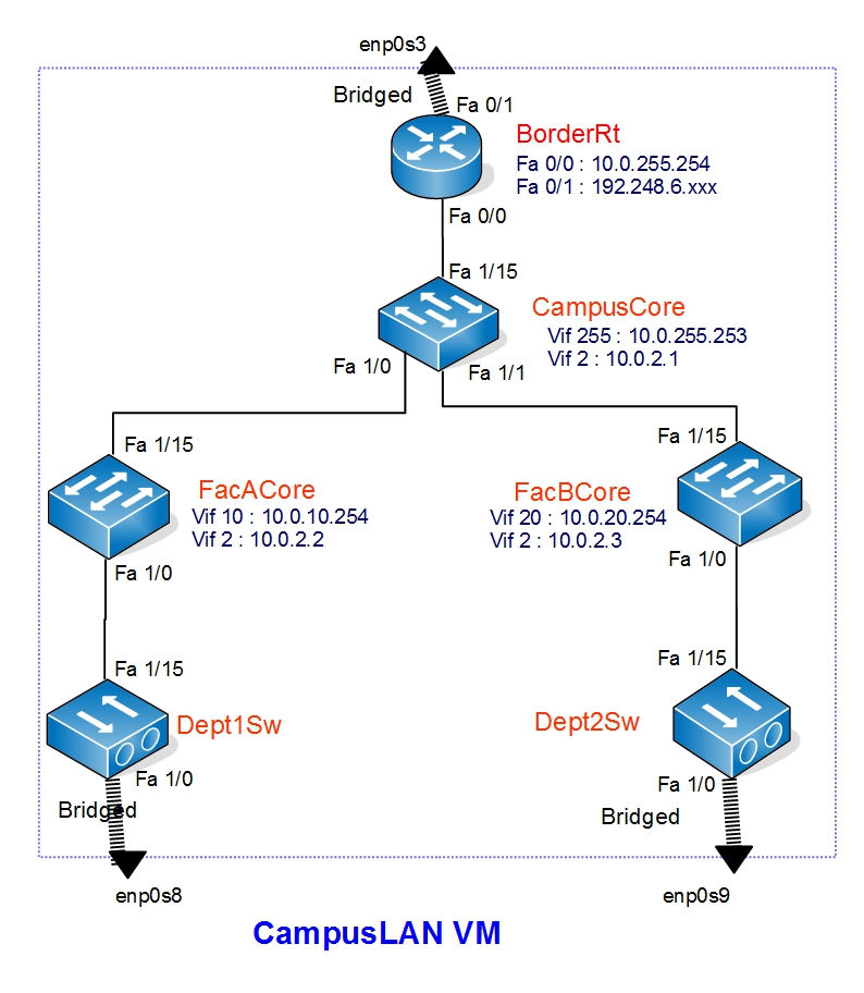
Network Configurations
See the following diagram to find the IPv4 address in devices

You can refer the following table for assign Interface IP's.
VLAN | VLAN Name | Device Name | VLAN Interface IP |
|---|---|---|---|
2 | Core | CampusCore | 10.0.2.1/24 |
FacACore | 10.0.2.2/24 | ||
FacBCore | 10.0.2.3/24 | ||
10 | FacA | FacACore | 10.0.10.254/24 |
Dept1PC | no interface IP | ||
20 | FacB | FacBCore | 10.0.20.254/24 |
Dept2PC | no interface IP | ||
255 | Router Connection/Public IP | CampusCore | 10.0.255.253/24 |
Refer the following table for the interface's switchport mode configuration
Device Name | Interface | Mode |
|---|---|---|
CampusCore | fast ethernet 1/15 | Access VLAN 255 |
fast ethernet 1/0 | Trunk | |
fast ethernet 1/1 | Trunk | |
FacACore | fast ethernet 1/15 | Trunk |
fast ethernet 1/0 | Trunk | |
FacBCore | fast ethernet 1/15 | Trunk |
fast ethernet 1/0 | Trunk | |
Dept1PC | fast ethernet 1/15 | Trunk |
fast ethernet 1/0 | Access VLAN 10 | |
Dept2PC | fast ethernet 1/15 | Trunk |
fast ethernet 1/0 | Access VLAN 20 | |
Core Network Layer
Let's start Configuring the connectivity between core network (CampusCore, FacACore and FacBCore). We will start from CampusCore.
- Login to CampusCore device. Give your console port password (class password)
- Go to config mode from user mode. Give your enable password (class password)
- Core network runs on VLAN 2. Create VLAN 2 and name it Core
CampusCore(config)# vlan 2
CampusCore(config-vlan)# name Core
CampusCore(config-vlan)# exit
- Then assign the IP Address to the VLAN interface. Get the IP from the table
CampusCore(config)#interface vlan 2
CampusCore(config-if)# ip address 10.0.2.1 255.255.255.0
CampusCore(config-if)# exit
- Finally configure fast ethernet interfaces switchport modes. You can find then from the table
- Fisrt make the interface a trunk port. This is for the FacACore link
CampusCore(config)#interface FastEthernet 1/0
CampusCore(config-if)#switchport mode trunk
- Define the encapsulation
CampusCore(config-if)#switchport trunk encapsulation dot1q
- Give the Description of the interface
CampusCore(config-if)#description Core link to FacACore
CampusCore(config-if)#exit
- Follow the same procedure for FacBCore link
CampusCore(config)#interface FastEthernet 1/1
CampusCore(config-if)#switchport mode trunk
CampusCore(config-if)#switchport trunk encapsulation dot1q
CampusCore(config-if)#description Core link to FacBCore
CampusCore(config-if)#exit
- Fisrt make the interface a trunk port. This is for the FacACore link
- You have successfully configured the CampusCore device for you core networks connectivity. Let's move on to FacACore device.
FacACore(config)# vlan 2
FacACore(config-vlan)# name Core
FacACore(config-vlan)# exit
FacACore(config)#interface vlan 2
FacACore(config-if)# ip address 10.0.2.2 255.255.255.0
FacACore(config-if)# exit
FacACore(config)#interface FastEthernet 1/15
FacACore(config-if)#switchport mode trunk
FacACore(config-if)#switchport trunk encapsulation dot1q
FacACore(config-if)#description Core link to CampusCore
FacACore(config-if)#exit
- Now let's configure FacBCore
FacBCore(config)# vlan 2
FacBCore(config-vlan)# name Core
FacBCore(config-vlan)# exit
FacBCore(config)#interface vlan 2
FacBCore(config-if)# ip address 10.0.2.3 255.255.255.0
FacBCore(config-if)# exit
FacBCore(config)#interface FastEthernet 1/15
FacBCore(config-if)#switchport mode trunk
FacBCore(config-if)#switchport trunk encapsulation dot1q
FacBCore(config-if)#description Core link to CampusCore
FacBCore(config-if)#exit
- Finally Verify the connectivity
- Go to FacACore device
- Go to privileged mode and ping CampusCore and FacBCore
ping 10.0.2.1
ping 10.0.2.3
- You should get a positive reply with "!!"
Distribution Network Layer
Let's Start Configuring the distribution layer of your campus LAN. Here you will have to configure both Layer 3 switches (FacACore and FacBCore) and Layer 2 Switches (Dept1PC and Dept2PC). Let's start from Layer 3 devices.
- Login to FacACore device
- Go to config mode from privileged mode
- FacACore is the Core device in Faculty A and It can have different departments. In this scenario department 1 is in faculty A and It's VLAN is VLAN10. Create VLAN 10 and Name it Dept1
FacACore(config)# vlan 10
FacACore(config-vlan)# name Dept1
FacACore(config-vlan)# exit
- Then assign the IP Address to the VLAN interface. Get the IP from the table
FacACore(config)#interface vlan 10
FacACore(config-if)# ip address 10.0.10.254 255.255.255.0
FacACore(config-if)# exit
- Next configure fast ethernet interfaces switchport modes. You can find then from the table
- Fisrt make the interface a trunk port.
FacACore(config)#interface FastEthernet 1/0
FacACore(config-if)#switchport mode trunk
- Define the encapsulation
FacACore(config-if)#switchport trunk encapsulation dot1q
- Give the Description of the interface
FacACore(config-if)#description link to Dept1Sw
FacACore(config-if)#exit
- Fisrt make the interface a trunk port.
- Follow the same procedure for FacBCore device. VLAN 20 name is dept 2.
FacBCore(config)# vlan 20
FacBCore(config-vlan)# name Dept2
FacBCore(config-vlan)# exit
FacBCore(config)#interface vlan 20
FacBCore(config-if)# ip address 10.0.20.254 255.255.255.0
FacBCore(config-if)# exit
FacBCore(config)#interface FastEthernet 1/0
FacBCore(config-if)#switchport mode trunk
FacBCore(config-if)#switchport trunk encapsulation dot1q
FacBCore(config-if)#description link to Dept2Sw
FacBCore(config-if)#exit
- Now the Core devices are done, Let's Configure Layer 2 devices. Login to Dept1PC
- Go to config mode
- Create Vlan 10 and Give a Name
Dept1Sw(config)# vlan 10
Dept1Sw(config-vlan)# name Dept1
Dept1Sw(config-vlan)# exit
- Next configure fast ethernet interface which connects to the Core device and give a description
Dept1Sw(config)#interface FastEthernet 1/15
Dept1Sw(config-if)#switchport mode trunk
Dept1Sw(config-if)#switchport trunk encapsulation dot1q
Dept1Sw(config-if)#description link to FacACore
Dept1Sw(config-if)#exit
- Configure fast ethernet interface, which connects to the User PC to an access port of VLAN 10 and give a description
Dept1Sw(config)#interface FastEthernet 1/0
Dept1Sw(config-if)#switchport mode access
Dept1Sw(config-if)#switchport access vlan 10
Dept1Sw(config-if)#description link to Dept1PC
Dept1Sw(config-if)#exit
- Follow the same steps for Dept2Sw
Dept2Sw(config)# vlan 20
Dept2Sw(config-vlan)# name Dept2
Dept2Sw(config-vlan)# exit
Dept2Sw(config)#interface FastEthernet 1/15
Dept2Sw(config-if)#switchport mode trunk
Dept2Sw(config-if)#switchport trunk encapsulation dot1q
Dept2Sw(config-if)#description link to FacBCore
Dept2Sw(config-if)#exit
Dept2Sw(config)#interface FastEthernet 1/0
Dept2Sw(config-if)#switchport mode access
Dept2Sw(config-if)#switchport access vlan 20
Dept2Sw(config-if)#description link to Dept2PC
Dept2Sw(config-if)#exit
- You have configured your distribution layer. Check and verify the connectivity
- Go to Dept1PC and try ping the gateway (VLAN 10 Interface IP of FacACore)
ping 10.0.10.254
- You should get a reply
- Try the same in Dept2PC
- Go to Dept1PC and try ping the gateway (VLAN 10 Interface IP of FacACore)
Connecting LAN to the Router
Your Campus LAN is connecting to the outside through a border router. Your CampusCore switch connects to this border router. In this link router's fast ethernet interface IP connects with the Core switch's vlan interface IP. Let's start configuring this link starting from the CampusCore.
- Login to CampusCore switch and switch to config mode
- Create VLAN 255 and name it Public
CampusCore(config)# vlan 255
CampusCore(config-vlan)# name Public
CampusCore(config-vlan)# exit
- Then assign the IP Address to the VLAN interface. Get the IP from the table. In the real situation this VLAN could be a public IP range which is assign to your Institute. In this Lab we are using a private IP block.
CampusCore(config)#interface vlan 255
CampusCore(config-if)# ip address 10.0.255.253 255.255.255.0
CampusCore(config-if)# exit
- Next configure fast ethernet interface which connects to the Core device and give a description.You can find then from the table
CampusCore(config)#interface FastEthernet 1/15
CampusCore(config-if)#switchport mode access
CampusCore(config-if)#switchport access vlan 255
CampusCore(config-if)#description link to Border Router
CampusCore(config-if)#speed 100
CampusCore(config-if)#duplex full
CampusCore(config-if)#exit
Note: In the real environment you might not need Duplex and Speed. It will be negotiate automatically
- Now you have done CampusCore configuration. Let's start routers Configuration.
- Login to BorderRt Router and switch to config mode
- Router's IP allocation is as follows. You can get your Router's IP address from here
| Interface Name | IP Address |
|---|---|
| Fast Ethernet 0/0 | 10.0.255.254/24 |
| Fast Ethernet 0/1 | <Your Routers WAN IP> |
- Let's configure the LAN port (fa 0/0)
BorderRt(config)#interface fastEthernet 0/0
BorderRt(config-if)#ip address 10.0.255.254 255.255.255.0
BorderRt(config-if)#description LAN Port connects to CampusCore
BorderRt(config-if)#no shutdown
BorderRt(config-if)#speed 100
BorderRt(config-if)#duplex full
BorderRt(config-if)#exit
- Configure the WAN port (fa 0/1)
BorderRt(config)#interface fastEthernet 0/1
BorderRt(config-if)#ip address x.x.x.x 255.255.255.0
BorderRt(config-if)#description WAN Port Bridged with CampusLAN host
BorderRt(config-if)#no shutdown
BorderRt(config-if)#exit
- You have successfully finished connecting CampusCore to the BorderRt router. Let's verify the connectivity using the ping command.
- Go to BorderRt and ping to CampusCore switch's VLAN 255 Interface IP
ping 10.0.255.253
- Now Check the routers connectivity in WAN port. Ping to the WAN Gateway
ping 192.248.6.254
- Both these ping commands should give you a reply
Routing
If You go to the Dept1PC and try a Ping to Dept2PC (10.0.20.1) and BorderRt router LAN port(10.0.255.254), you will not get a reply. That is because you don't have inter VLAN routing yet. In this Lab we will enable OSPF in all the Layer 3 devices and we will add default routes as following table.
- Following are the default routes of the devices
| Device | Default Route Destination IP | Default Route Destination Description |
|---|---|---|
| BorderRt | 192.248.6.254 | This is Configured in the router in the Lab |
| CampusCore | 10.0.255.254 | BorderRt routers LAN interface IP |
| FacACore | 10.0.2.1 | CampusCore Switches VLAN2 Interface IP |
| FacBCore | 10.0.2.1 | CampusCore Switches VLAN2 Interface IP |
| Dept1PC | none | This is a L2 device |
| Dept2PC | none | This is a L2 device |
| Dept1PC | 10.0.10.254 | FacACore Switches VLAN10 Interface IP |
| Dept2PC | 10.0.20.254 | FacBCore Switches VLAN20 Interface IP |
- Now let's enable OSPF on Core devices. Starting from CampusCore
- Login to CampusCore switch and switch to config mode
- Define OSPF process and Process ID. In this lab use process ID as 1
CampusCore(config)#router ospf 1
- Give the router ID
CampusCore(config-router)#router-id 10.0.2.1
- You are going to announce the subnets which are directly connects to you. Use this command for that
CampusCore(config-router)#redistribute connected subnets
- You are announcing to the core network (10.0.2.0/24) in area 2. Use this command for this
CampusCore(config-router)#network 10.0.2.0 0.0.0.255 area 2
CampusCore(config-router)#exit
- You are enabling OSPF on VLAN 2. Use this command for that.
CampusCore(config)#interface vlan 2
CampusCore(config-if)# ip ospf 1 area 2
CampusCore(config-if)# exit
- Now you have enable OSPF on CampusCore Switch. Now lets add the default Route.
CampusCore(config)# ip route 0.0.0.0 0.0.0.0 10.0.255.254
- Follow the same steps in FacACore and FacBCore
- FacACore
FacACore(config)#router ospf 1
FacACore(config-router)#router-id 10.0.2.2
FacACore(config-router)#redistribute connected subnets
FacACore(config-router)#network 10.0.2.0 0.0.0.255 area 2
FacACore(config-router)#exit
FacACore(config)#interface vlan 2
FacACore(config-if)# ip ospf 1 area 2
FacACore(config-if)# exit
FacACore(config)# ip route 0.0.0.0 0.0.0.0 10.0.2.1
- FacBCore
FacBCore(config)#router ospf 1
FacBCore(config-router)#router-id 10.0.2.3
FacBCore(config-router)#redistribute connected subnets
FacBCore(config-router)#network 10.0.2.0 0.0.0.255 area 2
FacBCore(config-router)#exit
FacBCore(config)#interface vlan 2
FacBCore(config-if)# ip ospf 1 area 2
FacBCore(config-if)# exit
FacBCore(config)# ip route 0.0.0.0 0.0.0.0 10.0.2.1
- FacACore
- Now you have enable Routing in your Core network. Let's verify whether it is working.
- Go to Dept1PC and try a Ping to Dept2PC
ping 10.0.20.1
- Try a ping to Router's LAN port
ping 10.0.255.254
- Both should give you a reply
- Go to Dept1PC and try a Ping to Dept2PC
- add the BorderRt Routers default gateway
- Go to BorderRt and switch to config mode
- Add the default route
BorderRt(config)# ip route 0.0.0.0 0.0.0.0 192.248.6.254
- Verify the route by ping a known host from the BorderRt router
ping 192.248.1.161
ping www.google.com
- Both should give you a reply
- Some troubleshooting commands
- You can get the routing table by following
Router#show ip route
- To get OSPF routes
Router#show ip route ospf
- To get ospf neighbors
Router#show ip ospf neighbor
- To reset OSPF process
clear ip ospf process
- You can get the routing table by following
Router Configuration
Now you have complete most of the IPv4 Configurations. Go to DeptPC1 and try a ping to the DNS server (192.248.1.161). You will not get a reply. That is because your PC have a private IP. There must be a method to connect to the outside using a private IP. What we use here is adding a NAT in BorderRt router. There are different NAT types what we use here is the method called NAT overload. In this method we can assign set of local(private) IP's and overload it to a interface with a global(public) IP. So the outside the network will see the traffic coming from local IP's as traffic coming from the global IP. Let's add this configuration to your router.
- Login to BorderRt Router and switch to config mode
- Let's define the local IP set in a ACL.
BorderRt(config)#access-list 1 permit 10.0.0.0 0.0.255.255
- Then dd the NAT entry. In your router public IP is assign to FastEthernet 0/1 interface
BorderRt(config)#ip nat inside source list 1 interface FastEthernet0/1 overload
- Then define NAT inside & NAT outside. NAT inside is your router's LAN port and Nat outside is your router's WAN port.
BorderRt(config)#interface FastEthernet 0/0
BorderRt(config-if)#ip nat inside
BorderRt(config-if)#exit
BorderRt(config)#interface FastEthernet 0/1
BorderRt(config-if)#ip nat outside
BorderRt(config-if)#exit
- Finally add a static route in the router so that the traffic coming to our defined network will redirect to CampusCore switch
BorderRt(config)#ip route 10.0.0.0 255.255.0.0 10.0.255.253
- Now try a ping from DeptPC1 to the DNS server. It should give reply
- Use the following for NAT troubleshooting
Router#show ip nat translation
You have successfully complete the IPv4 configurations. save all the configurations in all the routers
Wireshark
Let's capture some packets and do a analysis.
- Log in to Dept1PC and and start blackbox.
sudo startx
- Right click on desktop and open xterm terminal
- type wireshark and press enter
- On the wireshark interface select the enp0s3 interface and click Capture packets button
- While you are capturing. Open another xterm terminal. And type midori and press enter.
- You will get midori browser. Click the arrow head at top right corner to get the menu. In the menu select New Private Browsing Window
- Browse for www.google.com from the browser.
- Go back to wireshark and stop capturing
- You will see plenty of broadcast packets. They will look like following
NO	Time		Source			Destination	Protocol	Length	Info
9	0.579325000	00:fe:c9:3e:13:a0	Broadcast	ARP		60	Who has x.x.x.x?  Tell y.y.y.y
- Click on Statistics and select Summary
- You will get a summary window and it will show you some percentages. You will see a high percentage of ARP messages.
- Go to file in main menu and click close and exit without saving
- You will get the initial interface. Select enp0s3 interface
- click on the green flag in the using this filter... dropdown list.
- Select New capture filter:icmp6
- Start Capturing
Attachments (1)
- IPv4.jpg (213.8 KB ) - added by 9 years ago.
Download all attachments as: .zip