
| Version 13 (modified by , 9 years ago) ( diff ) |
|---|
Device Configuration
Now you have six inter connected devices. All those devices have no confurations in them and you have to configure them.
Remote Access
When you are working in the Virtualbox interface you can't copy and paste commands in to to that interface. You might have experienced this already. What you can do is you can remote log in to your campuslan VM.
Windows
- Download and run Putty
- type your campuslan VM's IP address in the hostname text box. set the port as 22
- Click open and You will ask the username and Password of your vm. Provide them and You will be able to remote login to your linux machine
Mac
- Open a terminal
- Type ssh learn@<Your campuslan VM's IP address>
- Give password and you will have a remote login to your linux machine
Log in to the the devices
In dynagen topology script you have to give a name to each device and there is a feature to assign a port to the console port of a particular device. Following are the device name and the console port number of your network setup.
| Device Name | Console Port Number |
|---|---|
| AccessRt | 2100 |
| CampusCore | 2200 |
| FacACore | 2300 |
| FacBCore | 2400 |
| FacASw | 2500 |
| FacBSw | 2600 |
You can use this port to log in to the device's console port. Use the following code
telnet localhost <console port number>
Now you have log in to your device. You can start configuring the device. After the configuration when you want to go back to host press cntl + } and you will get the following prompt.
telnet>
Type Quit to exit from telnet.
Initial Configurations
Before configure the devices for the network setup. Let's configure some initial settings in the router. If your router is boot up when you logged in you will be prompted to the following line.
Would you like to enter the initial configuration dialog? [yes/no]:
Type no (Might have to press the Enter key again) to go to the user mode of the router. Prompt will look as following.
Router>
In the user mode of the router give the command enable to go the privileged mode. Prompt will change to following
Router#
To add configurations you have to go configuration mode. Type config terminal. Note the prompt change.
Router(config)#
You can now start making configurations.
- First thing you have to add is the hostname of the device. Hostname is the device's identification. In this Lab device name is the same as host name. (Eg. CampusCore switch's hostname is CampusCore). Use the following command
hostname <device name>
You will see your prompt change from Router to the hostname you add.
- Then let's give a enable secret. Which is a password you set when you go to the privileged mode from the user mode. We will use the class password as the enable secret
enable secret <class password>
- Next you can add a banner to your device. This will display every time you log in to the device
banner motd @ Unauthorized Access is Prohibited! @
- Then lets's configure the line console which are the console port settings
- Go to line console config mode
line console 0
- Enable login authentication. Make sure not to save or exit the router after this command without executing the next command.
login
- Set the password
password <class password>
- Go to line console config mode
- Finally let's enable ssh (version 2) in the device. Type exit to go back to previous mode (config mode) from line console config mode
- Configure a domain name. Use learn.ac.lk for this lab.
ip domain name learn.ac.lk
- Create a ssh user with a password. In here we will use the username admin with the class pasword
username admin secret <class password>
- Create a certificate which will use for encryption
crypto key generate rsa
- Give the size of key as 768 (minimum size needed to activate ssh version 2)
- Then Configure the line vty
line vty 0 4
login local
transport input ssh
- Configure a domain name. Use learn.ac.lk for this lab.
Apply these settings in all six devices
Note : Hostname is different in each device
Network Configurations
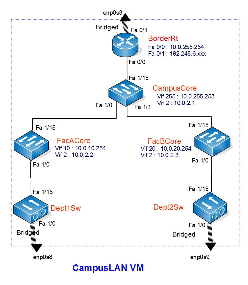
See the following diagram to find the IPv4 address in devices

You can refer the following table for assign Interface IP's.
VLAN | VLAN Name | Device Name | VLAN Interface IP |
|---|---|---|---|
2 | Core | CampusCore | 10.0.2.1/24 |
FacACore | 10.0.2.2/24 | ||
FacBCore | 10.0.2.3/24 | ||
10 | FacA | FacACore | 10.0.10.254/24 |
FacASw | no interface IP | ||
20 | FacB | FacBCore | 10.0.20.254/24 |
FacBSw | no interface IP | ||
255 | Router Connection/Public IP | CampusCore | 10.0.255.253/24 |
Refer the following table for the interface's switchport mode configuration
Device Name | Interface | Mode |
|---|---|---|
CampusCore | fast ethernet 1/15 | Access VLAN 255 |
fast ethernet 1/0 | Trunk | |
fast ethernet 1/1 | Trunk | |
FacACore | fast ethernet 1/15 | Trunk |
fast ethernet 1/0 | Trunk | |
FacBCore | fast ethernet 1/15 | Trunk |
fast ethernet 1/0 | Trunk | |
FacASw | fast ethernet 1/15 | Trunk |
fast ethernet 1/0 | Access VLAN 10 | |
FacBSw | fast ethernet 1/15 | Trunk |
fast ethernet 1/0 | Access VLAN 20 | |
Core Network Layer
Let's start Configuring the connectivity between core network (CampusCore, FacACore and FacBCore). We will start from CampusCore.
- Login to CampusCore device. Give your console port password (class password)
- Go to config mode from user mode. Give your enable password (class password)
- Core network runs on VLAN 2. Create VLAN 2 and name it Core
CampusCore(config)# vlan 2
CampusCore(config-vlan)# name Core
CampusCore(config-vlan)# exit
- Then assign the IP Address to the VLAN interface. Get the IP from the table
CampusCore(config)#interface vlan 2
CampusCore(config-if)# ip address 10.0.2.1 255.255.255.0
CampusCore(config-if)# exit
- Finally configure fast ethernet interfaces switchport modes. You can find then from the table
- Fisrt make the interface a trunk port. This is for the FacACore link
CampusCore(config)#interface FastEthernet 1/0
CampusCore(config-if)#switchport mode trunk
- Define the encapsulation
CampusCore(config-if)#switchport trunk encapsulation dot1q
- Give the Description of the interface
CampusCore(config-if)#description Core link to FacACore
CampusCore(config-if)#exit
- Follow the same procedure for FacBCore link
CampusCore(config)#interface FastEthernet 1/1
CampusCore(config-if)#switchport mode trunk
CampusCore(config-if)#switchport trunk encapsulation dot1q
CampusCore(config-if)#description Core link to FacACore
CampusCore(config-if)#exit
- Fisrt make the interface a trunk port. This is for the FacACore link
- You have successfully configured the CampusCore device for you core networks connectivity. Let's move on to FacACore device.
FacACore(config)# vlan 2
FacACore(config-vlan)# name Core
FacACore(config-vlan)# exit
FacACore(config)#interface vlan 2
FacACore(config-if)# ip address 10.0.2.2 255.255.255.0
FacACore(config-if)# exit
FacACore(config)#interface FastEthernet 1/15
FacACore(config-if)#switchport mode trunk
FacACore(config-if)#switchport trunk encapsulation dot1q
FacACore(config-if)#description Core link to CampusCore
FacACore(config-if)#exit
- Now let's configure FacBCore
FacBCore(config)# vlan 2
FacBCore(config-vlan)# name Core
FacBCore(config-vlan)# exit
FacBCore(config)#interface vlan 2
FacBCore(config-if)# ip address 10.0.2.3 255.255.255.0
FacBCore(config-if)# exit
FacBCore(config)#interface FastEthernet 1/15
FacBCore(config-if)#switchport mode trunk
FacBCore(config-if)#switchport trunk encapsulation dot1q
FacBCore(config-if)#description Core link to CampusCore
FacBCore(config-if)#exit
- Finally Verify the connectivity
- Go to FacACore device
- Go to privileged mode and ping CampusCore and FacBCore
ping 10.0.2.1
ping 10.0.2.3
- You should get a positive reply with "!!"
Distribution Network Layer
Let's Start Configuring the distribution layer of your campus LAN. Here you will have to configure both Layer 3 switches (FacACore and FacBCore) and Layer 2 Switches (FacASw and FacBSw). Let's start from Layer 3 devices.
- Login to FacACore device
- Go to config mode from privileged mode
- FacACore is the Core device in Faculty A and It can have different departments. In this scenario department 1 is in faculty A and It's VLAN is VLAN10. Create VLAN 10 and Name it Dept1
FacACore(config)# vlan 10
FacACore(config-vlan)# name Dept1
FacACore(config-vlan)# exit
- Then assign the IP Address to the VLAN interface. Get the IP from the table
FacACore(config)#interface vlan 10
FacACore(config-if)# ip address 10.0.10.254 255.255.255.0
FacACore(config-if)# exit
- Next configure fast ethernet interfaces switchport modes. You can find then from the table
- Fisrt make the interface a trunk port.
FacACore(config)#interface FastEthernet 1/0
FacACore(config-if)#switchport mode trunk
- Define the encapsulation
FacACore(config-if)#switchport trunk encapsulation dot1q
- Give the Description of the interface
FacACore(config-if)#description link to FacASw
FacACore(config-if)#exit
- Fisrt make the interface a trunk port.
- Follow the same procedure for FacBCore device. VLAN 20 name is dept 2.
FacBCore(config)# vlan 20
FacBCore(config-vlan)# name Dept2
FacBCore(config-vlan)# exit
FacBCore(config)#interface vlan 20
FacBCore(config-if)# ip address 10.0.20.254 255.255.255.0
FacBCore(config-if)# exit
FacBCore(config)#interface FastEthernet 1/0
FacBCore(config-if)#switchport mode trunk
FacBCore(config-if)#switchport trunk encapsulation dot1q
FacBCore(config-if)#description link to FacBSw
FacBCore(config-if)#exit
- Now the Core devices are done, Let's Configure Layer 2 devices. Login to FacASw
- Go to config mode
- Create Vlan 10 and Give a Name
FacASw(config)# vlan 10
FacASw(config-vlan)# name Dept1
FacASw(config-vlan)# exit
- Next configure fast ethernet interface which connects to the Core device and give a description
FacASw(config)#interface FastEthernet 1/15
FacASw(config-if)#switchport mode trunk
FacASw(config-if)#switchport trunk encapsulation dot1q
FacASw(config-if)#description link to FacACore
FacASw(config-if)#exit
- Configure fast ethernet interface, which connects to the User PC to an access port of VLAN 10 and give a description
FacASw(config-if)#switchport mode access
FacASw(config-if)#switchport access vlan 10
FacASw(config-if)#description link to Dept1PC
FacASw(config-if)#exit
- Follow the same steps for FacBSw
FacBSw(config)# vlan 20
FacBSw(config-vlan)# name Dept2
FacBSw(config-vlan)# exit
FacBSw(config)#interface FastEthernet 1/15
FacBSw(config-if)#switchport mode trunk
FacBSw(config-if)#switchport trunk encapsulation dot1q
FacBSw(config-if)#description link to FacBCore
FacBSw(config-if)#exit
FacBSw(config-if)#switchport mode access
FacBSw(config-if)#switchport access vlan 20
FacBSw(config-if)#description link to Dept2PC
FacBSw(config-if)#exit
- You have configured your distribution layer. Check and verify the connectivity
- Go to Dept1PC and try ping the gateway (VLAN 10 Interface IP of FacACore)
ping 10.0.10.254
- You should get a reply
- Try the same in Dept2PC
- Go to Dept1PC and try ping the gateway (VLAN 10 Interface IP of FacACore)
Attachments (1)
- IPv4.jpg (213.8 KB ) - added by 9 years ago.
Download all attachments as: .zip