
| Version 13 (modified by , 7 years ago) ( diff ) |
|---|
Campus Network Design - Network Setup
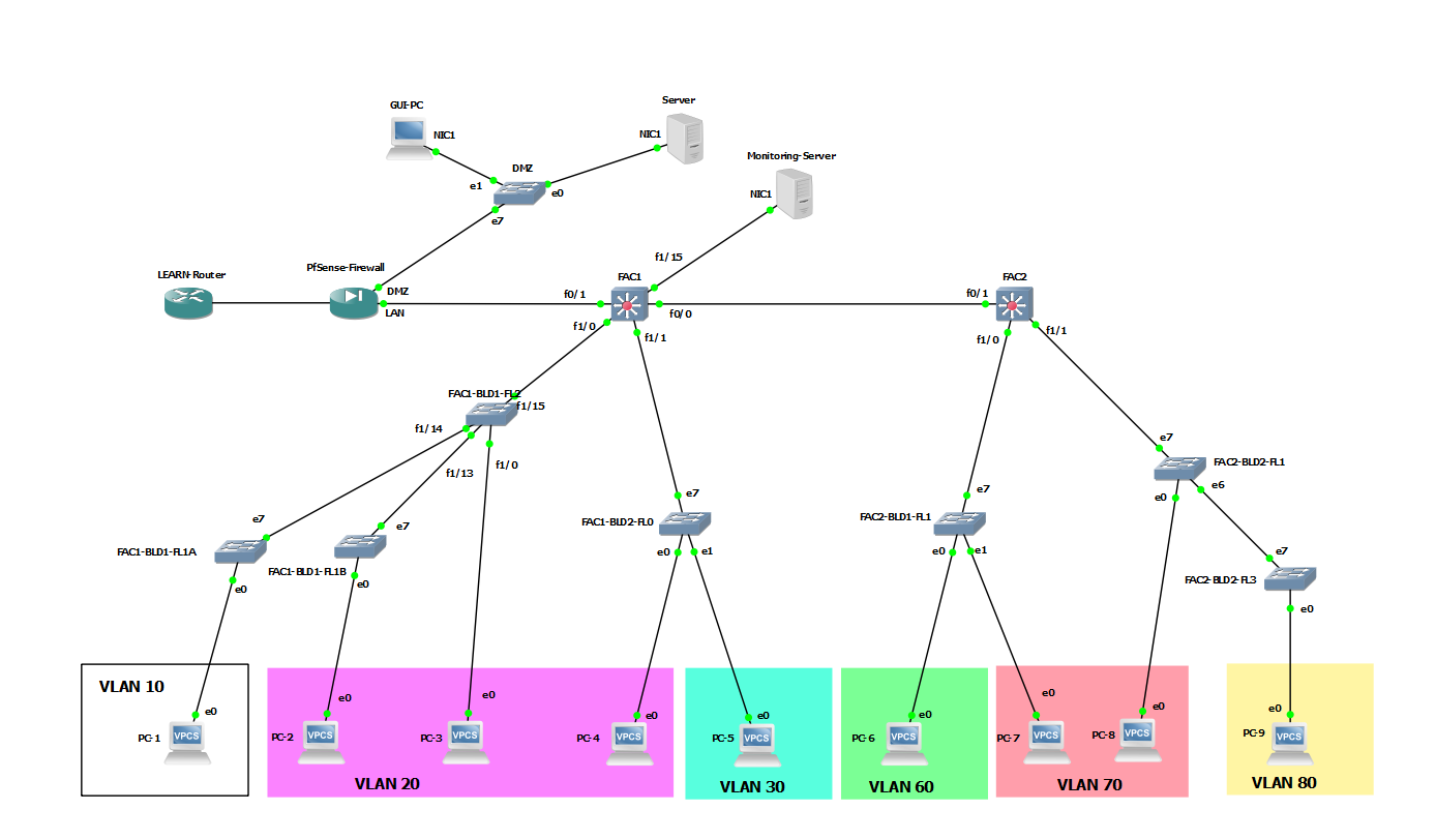
In this tutorial we will establish dual stack network connectivity within all nodes of the network given below.
IP Address Plan
| Device | Management IP Address | MGT Network | MGT VLAN |
|---|---|---|---|
| FAC1 | 10.XY.2.1 | 10.XY.2.0/24 | VLAN 2 |
| FAC1-BLD1-FL0 | | 10.XY.2.0/24 | VLAN 2 |
| FAC1-BLD1-FL1 | | 10.XY.2.0/24 | VLAN 2 |
| FAC1-BLD1-FL2 | 10.XY.2.4 | 10.XY.2.0/24 | VLAN 2 |
| FAC1-BLD2-FL0 | | 10.XY.2.0/24 | VLAN 2 |
| FAC2 | 10.XY.3.1 | 10.XY.3.0/24 | VLAN 3 |
| FAC2-BLD1-FL1 | | 10.XY.3.0/24 | VLAN 3 |
| FAC2-BLD2-FL1 | | 10.XY.3.0/24 | VLAN 3 |
| FAC2-BLD2-FL3 | | 10.XY.3.0/24 | VLAN 3 |
| FAC1 | Type | VLANS/IP | Native VLAN |
|---|---|---|---|
| F0/0 | Routed Link | 10.XY.0.6 2401:DD00:20XY:2::FFFF | - |
| F0/1 | Routed Link | 10.XY.0.1 2401:DD00:20XY:1::FFFE | - |
| F1/0 | Trunk | 10, 20 | 2 |
| F1/1 | Trunk | 20, 30 | 2 |
| F1/15 | Access | 1 | - |
| FAC2 | Type | VLANS/IP | Native VLAN |
|---|---|---|---|
| F0/1 | Routed Link | 10.XY.0.5 2401:dd00:20XY:2::FFFE | - |
| F1/0 | Trunk | 60, 70 | 3 |
| F1/1 | Trunk | 70, 80 | 3 |
| FAC1-BLD1-FL1 | Type | VLANS | Native VLAN |
|---|---|---|---|
| e0 | Access | 10 | - |
| e7 | Trunk | 10 | 2 |
| FAC1-BLD1-FL2 | Type | VLANS | Native VLAN |
|---|---|---|---|
| e0 | Access | 20 | - |
| e6 | Trunk | 10 | 2 |
| e7 | Trunk | 10, 20 | 2 |
| FAC1-BLD2-FL0 | Type | VLANS | Native VLAN |
|---|---|---|---|
| e0 | Access | 20 | - |
| e1 | Access | 30 | - |
| e7 | Trunk | 20, 30 | 2 |
| FAC2-BLD1-FL1 | Type | VLANS | Native VLAN |
|---|---|---|---|
| e0 | Access | 60 | - |
| e1 | Access | 70 | - |
| e7 | Trunk | 60, 70 | 3 |
| FAC2-BLD2-FL1 | Type | VLANS | Native VLAN |
|---|---|---|---|
| e0 | Access | 70 | - |
| e6 | Trunk | 80 | 3 |
| e7 | Trunk | 70, 80 | 3 |
| FAC2-BLD2-FL3 | Type | VLANS | Native VLAN |
|---|---|---|---|
| e0 | Access | 80 | - |
| e7 | Trunk | 80 | 3 |
| DMC | Type |
|---|---|
| e0 | Access |
| e1 | Access |
| e7 | Access |
| Host Devices | IPv4 | IPv6 |
|---|---|---|
| PC-1 | 10.XY.10.1 | 2401:DD00:20XY:1110::1/64 |
| PC-2 | 10.XY.20.1 | 2401:DD00:20XY:1120::1/64 |
| PC-3 | 10.XY.20.2 | 2401:DD00:20XY:1120::2/64 |
| PC-4 | 10.XY.30.1 | 2401:DD00:20XY:1230::1/64 |
| PC-5 | 10.XY.60.1 | 2401:DD00:20XY:2160::1/64 |
| PC-6 | 10.XY.70.1 | 2401:DD00:20XY:2270::1/64 |
| PC-7 | 10.XY.70.2 | 2401:DD00:20XY:2270::2/64 |
| PC-8 | 10.XY.80.1 | 2401:DD00:20XY:2280::1/64 |
| Monitoring-Server | 10.XY.5.LMN | 2401:DD00:20XY:5::AAAA/64 |
| Server | 192.168.XY.PQR | 2401:DD00:20XY:1::PQR/64 |
| GUI-PC | via DHCP | |
| FAC1 | IPv4 | IPv6 |
|---|---|---|
| VLAN02 | 10.XY.02.1 | - |
| VLAN05 | 10.XY.05.254 | 2401:DD00:20XY:5::FFFF/64 |
| VLAN10 | 10.XY.10.254 | 2401:DD00:20XY:1110::FFFF/64 |
| VLAN20 | 10.XY.20.254 | 2401:DD00:20XY:1120::FFFF/64 |
| VLAN30 | 10.XY.30.254 | 2401:DD00:20XY:1230::FFFF/64 |
| FAC2 | IPv4 | IPv6 |
|---|---|---|
| VLAN03 | 10.XY.03.1 | - |
| VLAN60 | 10.XY.60.254 | 2401:DD00:20XY:2160::FFFF/64 |
| VLAN70 | 10.XY.70.254 | 2401:DD00:20XY:2270::FFFF/64 |
| VLAN80 | 10.XY.80.254 | 2401:DD00:20XY:2280::FFFF/64 |
Log in to the the devices
In GNS3 topology right click on each network device and select Console. It will open your device console screen on a putty.
Initial Configurations
Before configuring the devices for the network setup. Let's configure some initial settings in the Core Network Devices.
Press the Enter key to go to the user mode of the FAC1 switch. Prompt will look as follows.
FAC1#
In this privileged mode, you can check the router configuration by the following command. The configuration you see will be the default configuration
FAC1#show run
To add configurations you have to go configuration mode. Type config terminal. Note the prompt change.
FAC1(config)#
note: If you get following error,
%Error opening tftp://255.255.255.255/AccessRt-confg (Timed out)
Give the following command in the config mode,
no service config
You can now start making configurations.
- The first thing you have to add is the hostname of the device. The hostname is the device's identification. In this Lab device name or the hostname is automatically configured based on the GUI edits we did previously. If you want to change it you may use
hostname <device name>
- Then let's give a enable secret. Which is a password you set when you go to the privileged mode from the user mode? We will use the class password as the enable secret
enable secret <class password>
- Add the DNS server
ip name-server 192.248.1.161
In your production environment you may use your internal DNS resolver if needed.
- Next, you can add a banner to your device. This will display every time you log in to the device
banner motd @ Unauthorized Access is Prohibited! @
- Add more security by encrypting passwords in your config file
service password-encryption
- Then lets's configure the line console which are the console port settings
- Go to line console config mode
line console 0
- Enable login authentication. Make sure not to save or exit the router after this command without executing the next command.
login
- Set the password
password <class password>
- Go to line console config mode
- Finally let's enable ssh (version 2) in the device. Type exit to go back to previous mode (config mode) from line console config mode
- Configure a domain name. Use instXY.learn.ac.lk for this lab where XY is your group id.
ip domain name instXY.learn.ac.lk
- Create an ssh user with a password. In here we will use the username admin with the class password
username admin secret <class password>
- Create a certificate which will use for encryption
crypto key generate rsa
- Give the size of key as 768 (minimum size needed to activate ssh version 2)
- Then Configure the line vty
line vty 0 4
login local
transport input ssh
- Configure a domain name. Use instXY.learn.ac.lk for this lab where XY is your group id.
- Now save the configurations. you have to Go to privileged mode and give the following command
#copy running-config startup-config
- Check the configuration by show run command.
Apply these settings in FAC2 and FAC1-BLD1-FL2 as well
Core Network Layer
Let's start Configuring the connectivity between the core network (FAC1 and Fac2). We will start with Fac1.
- Remember, the core network runs on routed ports. Get the IP from the table
- Link to Firewall
FAC1(config)# interface fastEthernet 0/1
FAC1(config-if)# description Link to Firewall
FAC1(config-if)# ip address 10.XY.0.1 255.255.255.252
FAC1(config-if)#ipv6 address 2401:dd00:20XY:1::fffe/128
FAC1(config-if)#no shutdown
FAC1(config-if)#exit
- Link to FAC2
FAC1(config)# interface fastEthernet 0/0
FAC1(config-if)# description Link to FAC2
FAC1(config-if)# ip address 10.XY.0.6 255.255.255.252
FAC1(config-if)#ipv6 address 2401:dd00:20XY:2::ffff/128
FAC1(config-if)#no shutdown
FAC1(config-if)#exit
- On switch FAC2 we have only one routed port. Get the IP from the table
- Link to FAC1
FAC2(config)# interface fastEthernet 0/1
FAC2(config-if)# description Link to FAC1
FAC2(config-if)# ip address 10.XY.0.5 255.255.255.252
FAC2(config-if)#ipv6 address 2401:dd00:20XY:2::fffe/128
FAC2(config-if)#no shutdown
FAC2(config-if)#exit
- Next, we need to configure routing among Core devices. We will configure dynamic routing / OSPF to distribute routing.
- On FAC1, Define OSPF process and Process ID. In this lab use process ID as 1
FAC1(config)#router ospf 1
- Give the router ID
FAC1(config-router)#router-id 10.XY.2.1
- You are announcing to the whole core network (10.XY.0.0/24) in area 2. Use this command for this
FAC1config-router)#network 10.XY.0.0 0.0.0.255 area 2
FAC1(config-router)#exit
- Now you have enable OSPF on FAC1 Switch. Now lets add the default Route.
FAC1(config)# ip route 0.0.0.0 0.0.0.0 10.XY.0.2
- On FAC1, Define OSPF process and Process ID. In this lab use process ID as 1
- Now let's enable routing for IPv6.
FAC1(config)# ipv6 unicast-routing
- Create a OSPF v3 instance, Define OSPF process and Process ID. In this lab use process ID as 1
FAC1(config)#ipv6 router ospf 1
- Give the router ID, this will be the same as ipv4 ospf router ID for simplicity
FAC1(config-rtr)#router-id 10.0.2.1
- You are going to announce the subnets which are directly connects to you. Use this command for that,
FAC1(config-rtr)#redistribute connected
FAC1(config-rtr)#exit
- Create the default route
FAC1(config)ipv6 route ::/0 2401:DD00:20XY:1::FFFF
- Create a OSPF v3 instance, Define OSPF process and Process ID. In this lab use process ID as 1
- Follow the same steps in FAC2
FAC2(config)#router ospf 1
FAC2(config-router)#router-id 10.XY.3.1
FAC2(config-router)#network 10.XY.0.0 0.0.0.255 area 2
FAC2(config-router)#exit
FAC2(config)# ip route 0.0.0.0 0.0.0.0 10.0.0.6
FAC1(config)# ipv6 unicast-routing
FAC1(config)#ipv6 router ospf 1
FAC2(config-rtr)#router-id 10.0.3.1
FAC2(config-rtr)#redistribute connected
FAC2(config-rtr)#exit
FAC1(config)ipv6 route ::/0 2401:DD00:20XY:2::FFFF
Distribution Layer
Temp Data
- Finally configure fast ethernet interfaces switchport modes. You can find then from the table
- Fisrt make the interface a trunk port. This is for the FacACore link
CampusCore(config)#interface FastEthernet 1/0
CampusCore(config-if)#switchport mode trunk
- Define the encapsulation
CampusCore(config-if)#switchport trunk encapsulation dot1q
- Give the Description of the interface
CampusCore(config-if)#description Core link to FacACore
CampusCore(config-if)#exit
- Follow the same procedure for FacBCore link
CampusCore(config)#interface FastEthernet 1/1
CampusCore(config-if)#switchport mode trunk
CampusCore(config-if)#switchport trunk encapsulation dot1q
CampusCore(config-if)#description Core link to FacBCore
CampusCore(config-if)#exit
- Fisrt make the interface a trunk port. This is for the FacACore link
- You have successfully configured the CampusCore device for you core networks connectivity. Let's move on to FacACore device.
FacACore(config)# vlan 2
FacACore(config-vlan)# name Core
FacACore(config-vlan)# exit
FacACore(config)#interface vlan 2
FacACore(config-if)# ip address 10.0.2.2 255.255.255.0
FacACore(config-if)# exit
FacACore(config)#interface FastEthernet 1/15
FacACore(config-if)#switchport mode trunk
FacACore(config-if)#switchport trunk encapsulation dot1q
FacACore(config-if)#description Core link to CampusCore
FacACore(config-if)#exit
- Now let's configure FacBCore
FacBCore(config)# vlan 2
FacBCore(config-vlan)# name Core
FacBCore(config-vlan)# exit
FacBCore(config)#interface vlan 2
FacBCore(config-if)# ip address 10.0.2.3 255.255.255.0
FacBCore(config-if)# exit
FacBCore(config)#interface FastEthernet 1/15
FacBCore(config-if)#switchport mode trunk
FacBCore(config-if)#switchport trunk encapsulation dot1q
FacBCore(config-if)#description Core link to CampusCore
FacBCore(config-if)#exit
- Finally Verify the connectivity
- Go to FacACore device
- Go to privileged mode and ping CampusCore and FacBCore
ping 10.0.2.1
ping 10.0.2.3
- You should get a positive reply with "!!"
Distribution Network Layer
Let's Start Configuring the distribution layer of your campus LAN. Here you will have to configure both Layer 3 switches (FacACore and FacBCore) and Layer 2 Switches (Dept1PC and Dept2PC). Let's start from Layer 3 devices.
- Login to FacACore device
- Go to config mode from privileged mode
- FacACore is the Core device in Faculty A and It can have different departments. In this scenario department 1 is in faculty A and It's VLAN is VLAN10. Create VLAN 10 and Name it Dept1
FacACore(config)# vlan 10
FacACore(config-vlan)# name Dept1
FacACore(config-vlan)# exit
- Then assign the IP Address to the VLAN interface. Get the IP from the table
FacACore(config)#interface vlan 10
FacACore(config-if)# ip address 10.0.10.254 255.255.255.0
FacACore(config-if)# exit
- Next configure fast ethernet interfaces switchport modes. You can find then from the table
- Fisrt make the interface a trunk port.
FacACore(config)#interface FastEthernet 1/0
FacACore(config-if)#switchport mode trunk
- Define the encapsulation
FacACore(config-if)#switchport trunk encapsulation dot1q
- Give the Description of the interface
FacACore(config-if)#description link to Dept1Sw
FacACore(config-if)#exit
- Fisrt make the interface a trunk port.
- Follow the same procedure for FacBCore device. VLAN 20 name is dept 2.
FacBCore(config)# vlan 20
FacBCore(config-vlan)# name Dept2
FacBCore(config-vlan)# exit
FacBCore(config)#interface vlan 20
FacBCore(config-if)# ip address 10.0.20.254 255.255.255.0
FacBCore(config-if)# exit
FacBCore(config)#interface FastEthernet 1/0
FacBCore(config-if)#switchport mode trunk
FacBCore(config-if)#switchport trunk encapsulation dot1q
FacBCore(config-if)#description link to Dept2Sw
FacBCore(config-if)#exit
- Now the Core devices are done, Let's Configure Layer 2 devices. Login to Dept1PC
- Go to config mode
- Create Vlan 10 and Give a Name
Dept1Sw(config)# vlan 10
Dept1Sw(config-vlan)# name Dept1
Dept1Sw(config-vlan)# exit
- Next configure fast ethernet interface which connects to the Core device and give a description
Dept1Sw(config)#interface FastEthernet 1/15
Dept1Sw(config-if)#switchport mode trunk
Dept1Sw(config-if)#switchport trunk encapsulation dot1q
Dept1Sw(config-if)#description link to FacACore
Dept1Sw(config-if)#exit
- Configure fast ethernet interface, which connects to the User PC to an access port of VLAN 10 and give a description
Dept1Sw(config)#interface FastEthernet 1/0
Dept1Sw(config-if)#switchport mode access
Dept1Sw(config-if)#switchport access vlan 10
Dept1Sw(config-if)#description link to Dept1PC
Dept1Sw(config-if)#exit
- Follow the same steps for Dept2Sw
Dept2Sw(config)# vlan 20
Dept2Sw(config-vlan)# name Dept2
Dept2Sw(config-vlan)# exit
Dept2Sw(config)#interface FastEthernet 1/15
Dept2Sw(config-if)#switchport mode trunk
Dept2Sw(config-if)#switchport trunk encapsulation dot1q
Dept2Sw(config-if)#description link to FacBCore
Dept2Sw(config-if)#exit
Dept2Sw(config)#interface FastEthernet 1/0
Dept2Sw(config-if)#switchport mode access
Dept2Sw(config-if)#switchport access vlan 20
Dept2Sw(config-if)#description link to Dept2PC
Dept2Sw(config-if)#exit
- You have configured your distribution layer. Check and verify the connectivity
- Go to Dept1PC and try ping the gateway (VLAN 10 Interface IP of FacACore)
ping 10.0.10.254
- You should get a reply
- Try the same in Dept2PC
- Go to Dept1PC and try ping the gateway (VLAN 10 Interface IP of FacACore)
Connecting LAN to the Router
Your Campus LAN is connecting to the outside through a border router. Your CampusCore switch connects to this border router. In this link router's fast ethernet interface IP connects with the Core switch's vlan interface IP. Let's start configuring this link starting from the CampusCore.
- Login to CampusCore switch and switch to config mode
- Create VLAN 255 and name it Public
CampusCore(config)# vlan 255
CampusCore(config-vlan)# name Public
CampusCore(config-vlan)# exit
- Then assign the IP Address to the VLAN interface. Get the IP from the table. In the real situation this VLAN could be a public IP range which is assign to your Institute. In this Lab we are using a private IP block.
CampusCore(config)#interface vlan 255
CampusCore(config-if)# ip address 10.0.255.253 255.255.255.0
CampusCore(config-if)# exit
- Next configure fast ethernet interface which connects to the Core device and give a description.You can find then from the table
CampusCore(config)#interface FastEthernet 1/15
CampusCore(config-if)#switchport mode access
CampusCore(config-if)#switchport access vlan 255
CampusCore(config-if)#description link to Border Router
CampusCore(config-if)#speed 100
CampusCore(config-if)#duplex full
CampusCore(config-if)#exit
Note: In the real environment you might not need Duplex and Speed. It will be negotiate automatically
- Now you have done CampusCore configuration. Let's start routers Configuration.
- Login to BorderRt Router and switch to config mode
- Router's IP allocation is as follows. You can get your Router's IP address from here
| Interface Name | IP Address |
|---|---|
| Fast Ethernet 0/0 | 10.0.255.254/24 |
| Fast Ethernet 0/1 | <Your Routers WAN IP> |
- Let's configure the LAN port (fa 0/0)
BorderRt(config)#interface fastEthernet 0/0
BorderRt(config-if)#ip address 10.0.255.254 255.255.255.0
BorderRt(config-if)#description LAN Port connects to CampusCore
BorderRt(config-if)#no shutdown
BorderRt(config-if)#speed 100
BorderRt(config-if)#duplex full
BorderRt(config-if)#exit
- Configure the WAN port (fa 0/1)
BorderRt(config)#interface fastEthernet 0/1
BorderRt(config-if)#ip address x.x.x.x 255.255.255.0
BorderRt(config-if)#description WAN Port Bridged with CampusLAN host
BorderRt(config-if)#no shutdown
BorderRt(config-if)#exit
- You have successfully finished connecting CampusCore to the BorderRt router. Let's verify the connectivity using the ping command.
- Go to BorderRt and ping to CampusCore switch's VLAN 255 Interface IP
ping 10.0.255.253
- Now Check the routers connectivity in WAN port. Ping to the WAN Gateway
ping 192.248.6.254
- Both these ping commands should give you a reply
Routing
If You go to the Dept1PC and try a Ping to Dept2PC (10.0.20.1) and BorderRt router LAN port(10.0.255.254), you will not get a reply. That is because you don't have inter VLAN routing yet. In this Lab we will enable OSPF in all the Layer 3 devices and we will add default routes as following table.
- Following are the default routes of the devices
| Device | Default Route Destination IP | Default Route Destination Description |
|---|---|---|
| BorderRt | 192.248.6.254 | This is Configured in the router in the Lab |
| CampusCore | 10.0.255.254 | BorderRt routers LAN interface IP |
| FacACore | 10.0.2.1 | CampusCore Switches VLAN2 Interface IP |
| FacBCore | 10.0.2.1 | CampusCore Switches VLAN2 Interface IP |
| Dept1PC | none | This is a L2 device |
| Dept2PC | none | This is a L2 device |
| Dept1PC | 10.0.10.254 | FacACore Switches VLAN10 Interface IP |
| Dept2PC | 10.0.20.254 | FacBCore Switches VLAN20 Interface IP |
- Now let's enable OSPF on Core devices. Starting from CampusCore
- Login to CampusCore switch and switch to config mode
- Define OSPF process and Process ID. In this lab use process ID as 1
CampusCore(config)#router ospf 1
- Give the router ID
CampusCore(config-router)#router-id 10.0.2.1
- You are going to announce the subnets which are directly connects to you. Use this command for that
CampusCore(config-router)#redistribute connected subnets
- You are announcing to the core network (10.0.2.0/24) in area 2. Use this command for this
CampusCore(config-router)#network 10.0.2.0 0.0.0.255 area 2
CampusCore(config-router)#exit
- You are enabling OSPF on VLAN 2. Use this command for that.
CampusCore(config)#interface vlan 2
CampusCore(config-if)# ip ospf 1 area 2
CampusCore(config-if)# exit
- Now you have enable OSPF on CampusCore Switch. Now lets add the default Route.
CampusCore(config)# ip route 0.0.0.0 0.0.0.0 10.0.255.254
- Follow the same steps in FacACore and FacBCore
- FacACore
FacACore(config)#router ospf 1
FacACore(config-router)#router-id 10.0.2.2
FacACore(config-router)#redistribute connected subnets
FacACore(config-router)#network 10.0.2.0 0.0.0.255 area 2
FacACore(config-router)#exit
FacACore(config)#interface vlan 2
FacACore(config-if)# ip ospf 1 area 2
FacACore(config-if)# exit
FacACore(config)# ip route 0.0.0.0 0.0.0.0 10.0.2.1
- FacBCore
FacBCore(config)#router ospf 1
FacBCore(config-router)#router-id 10.0.2.3
FacBCore(config-router)#redistribute connected subnets
FacBCore(config-router)#network 10.0.2.0 0.0.0.255 area 2
FacBCore(config-router)#exit
FacBCore(config)#interface vlan 2
FacBCore(config-if)# ip ospf 1 area 2
FacBCore(config-if)# exit
FacBCore(config)# ip route 0.0.0.0 0.0.0.0 10.0.2.1
- FacACore
- Now you have enable Routing in your Core network. Let's verify whether it is working.
- Go to Dept1PC and try a Ping to Dept2PC
ping 10.0.20.1
- It should give you a reply
- Go to Dept1PC and try a Ping to Dept2PC
- add the BorderRt Routers default gateway
- Go to BorderRt and switch to config mode
- Add the default route
BorderRt(config)# ip route 0.0.0.0 0.0.0.0 192.248.6.254
- Verify the route by ping a known host from the BorderRt router
ping 192.248.1.161
ping www.google.com
- Both should give you a reply
- Some troubleshooting commands
- You can get the routing table by following
Router#show ip route
- To get OSPF routes
Router#show ip route ospf
- To get ospf neighbors
Router#show ip ospf neighbor
- To reset OSPF process
clear ip ospf process
- You can get the routing table by following
Router Configuration
Now you have complete most of the IPv4 Configurations. Go to DeptPC1 and try a ping to the DNS server (192.248.1.161). You will not get a reply. That is because your PC have a private IP. There must be a method to connect to the outside using a private IP. What we use here is adding a NAT in BorderRt router. There are different NAT types what we use here is the method called NAT overload. In this method we can assign set of local(private) IP's and overload it to a interface with a global(public) IP. So the outside the network will see the traffic coming from local IP's as traffic coming from the global IP. Let's add this configuration to your router.
- Login to BorderRt Router and switch to config mode
- Let's define the local IP set in a ACL.
BorderRt(config)#access-list 1 permit 10.0.0.0 0.0.255.255
- Then dd the NAT entry. In your router public IP is assign to FastEthernet 0/1 interface
BorderRt(config)#ip nat inside source list 1 interface FastEthernet0/1 overload
- Then define NAT inside & NAT outside. NAT inside is your router's LAN port and Nat outside is your router's WAN port.
BorderRt(config)#interface FastEthernet 0/0
BorderRt(config-if)#ip nat inside
BorderRt(config-if)#exit
BorderRt(config)#interface FastEthernet 0/1
BorderRt(config-if)#ip nat outside
BorderRt(config-if)#exit
- Finally add a static route in the router so that the traffic coming to our defined network will redirect to CampusCore switch
BorderRt(config)#ip route 10.0.0.0 255.255.0.0 10.0.255.253
- Now try a ping from DeptPC1 to the DNS server. It should give reply
- Use the following for NAT troubleshooting
Router#show ip nat translation
You have successfully complete the IPv4 configurations. save all the configurations in all the routers
Wireshark
Let's capture some packets and do a analysis.
- Log in to Dept1PC and and start blackbox.
sudo startx
- Right click on desktop and open xterm terminal
- type wireshark and press enter
- On the wireshark interface select the enp0s3 interface and click Capture packets button
- While you are capturing. Open another xterm terminal. And type midori and press enter.
- You will get midori browser. Click the arrow head at top right corner to get the menu. In the menu select New Private Browsing Window
- Browse for www.google.com from the browser.
- Go back to wireshark and stop capturing
- You will see plenty of broadcast packets. They will look like following
NO	Time		Source			Destination	Protocol	Length	Info
9	0.579325000	00:fe:c9:3e:13:a0	Broadcast	ARP		60	Who has x.x.x.x?  Tell y.y.y.y
- Click on Statistics and select Summary
- You will get a summary window and it will show you some percentages. You will see a high percentage of ARP messages.
- Go to file in main menu and click close and exit without saving
- You will get the initial interface. Select enp0s3 interface
- click on the green flag in the using this filter... dropdown list.
- Select New capture filter:icmp6
- Start Capturing
Attachments (1)
- vlans.png (134.6 KB ) - added by 7 years ago.
Download all attachments as: .zip